
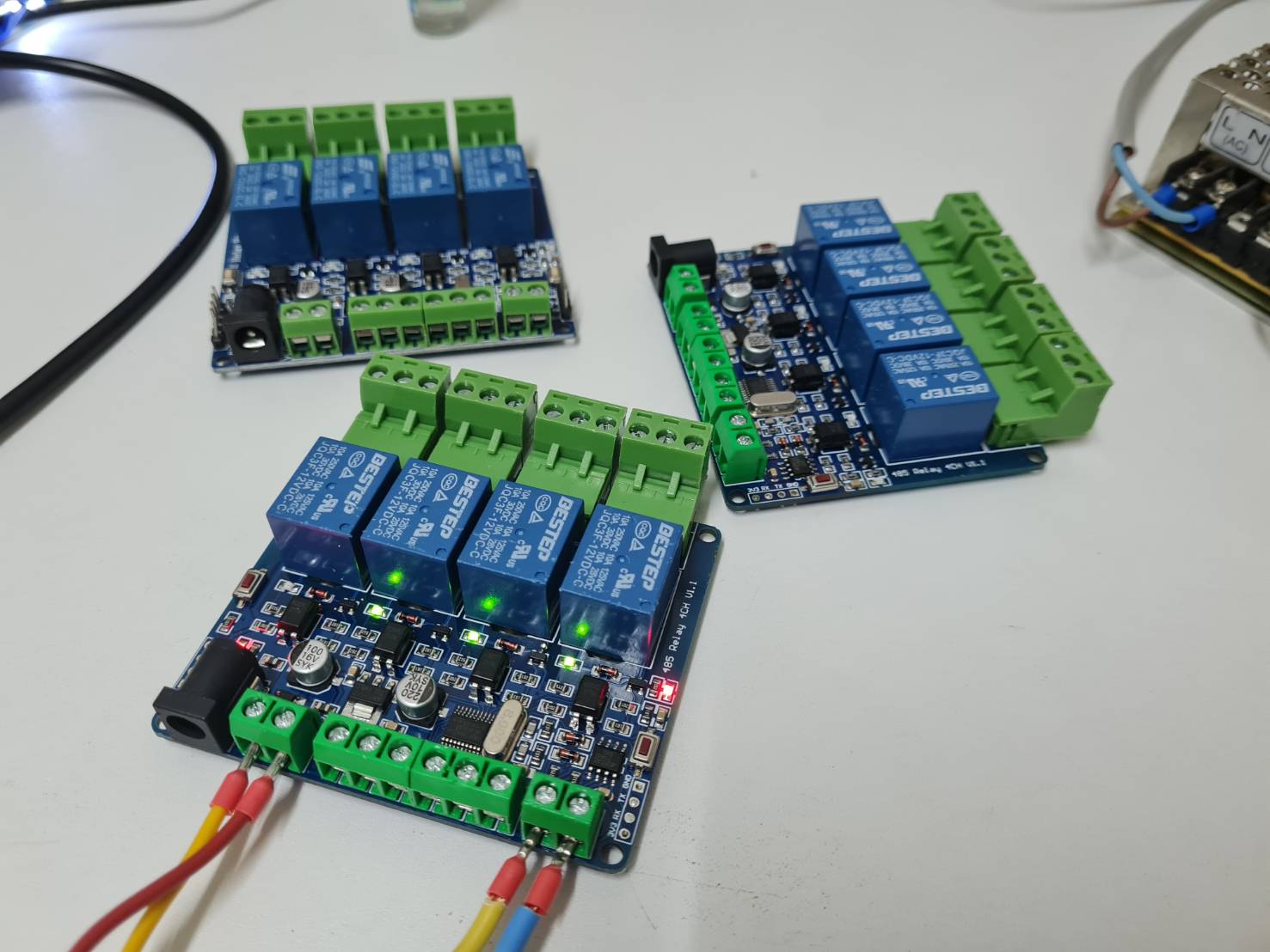
Modbus RTU 4CH relay module RS485 4 Channel Relay 12V RS485 V1.1
Modbus RTU introduction of instruction
Modbus device through receive from external control terminal (like Host computer/MCU )Modbus RTU instruction to perform related operations, one frame instruction generally consists of device address, function code, register address, register data, and check code,frame length is related to function code. Each frame date’s first byte is the device address.can set range on 1-255 default 255(scilicet 0xFF),the last 2byte is CRC check code.
suppose the device address is 255, the commonly used Modbus RTU instructions are as follows:
1, turn on the relay No. 1 (manual mode)
send : FF 05 00 00 FF 00 99 E4
return :FF 05 00 00 FF 00 99 E4
remarks:(1)send the 3--4th byte of the transmitted frame represents the relay address,the relay 1-relay 8 address are respectively 0x0000,0x0001,0x0002,0x0003,0x0004,0x0005,0x0006,0x0007.
(2)The 5--6th byte of the transmitted frame represents the data, 0xFF00 represent turn on relay,0x0000 represent turn off relay.
2, turn off the relay No. 1 (manual mode)
send: FF 05 00 00 00 00 D8 14
return: FF 05 00 00 00 00 D8 14
3, turn on the relay no.2 (manual mode)
send : FF 05 00 01 FF 00 C8 24
return : FF 05 00 01 FF 00 C8 24
4, turn off the relay No. 2 (manual mode)
send :FF 05 00 01 00 00 89 D4
return :FF 05 00 01 00 00 89 D4
5, turn on all relay
send :FF 0F 00 00 00 08 01 FF 30 1D
return :FF 0F 00 00 00 08 41 D3
6,turn off all relay
send:FF 0F 00 00 00 08 01 00 70 5D
return :FF 0F 00 00 00 08 41 D3
7, set the device address to 1
Send :00 10 00 00 00 01 02 00 01 6A 00
return :00 10 00 00 00 01 02 00 01 6A 00
remark:The 9th byte of the transmitted frame,0x01 is the written device address.
8, Set the device address to 255
send: 00 10 00 00 00 01 02 00 FF EB 80
return : 00 10 00 00 00 01 02 00 FF EB 80
remarks:The 9th byte of the transmitted frame, 0xFF is the written device address.
9,read device address
send :00 03 00 00 00 01 85 DB
return :00 03 02 00 FF C5 C4
remarks:The 5th byte of the Return frame, 0xFF is the read device address.
10,read device address
send:FF 01 00 00 00 08 28 12
return :FF 01 01 01 A1 A0
remarks:The 4th byte of the Return frame,the Bit0--Bit7 of 0x01 representing relay 1-relay 8, 0 is turn off .1 is turn on.
11, Read optocoupler input status
send:FF 02 00 00 00 08 6C 12
return :FF 02 01 01 51 A0
remarks: The 4th byte of the Return frame, the Bit0--Bit7 of 0x01 represent input signal of optocoupler1- optocoupler 8, 0 represent low level ,1 represent high level
12,Set the baud rate to 4800
send:FF 10 03 E9 00 01 02 00 02 4A 0C
return:FF 10 03 E9 00 01 C5 A7
remarks: The 9th byte of the transmitted frame is the baud rate setting value, 0x02, 0x03, 0x04 represents 4800, 9600, 19200
13,Set the baud rate to 9600
send:FF 10 03 E9 00 01 02 00 03 8B CC
return:FF 10 03 E9 00 01 C5 A7
14,Set the baud rate to 19200
send:FF 10 03 E9 00 01 02 00 04 CA 0E
return:FF 10 03 E9 00 01 C5 A7
15,Read the baud rate
send: FF 03 03 E8 00 01 11 A4
return :FF 03 02 00 04 90 53
remarks:The 5th byte of the Return frame represent read baud rate, 0x02, 0x03, x04 represents 4800,9600,19200.
16, turn on no.1 relay (flash off mode)
send :FF 10 00 03 00 02 04 00 04 00 14 C5 9F
return : FF 10 00 03 00 02 A4 16
remarks: the 3-4th byte of the transmitted frame is represent relay address,relay1-relay8’s address separately is 0x0003,0x0008,0x000D,0x0012,0x0017,0x001C,0x0021,0x0026 .
The 10th-11th byte of the transmitted frame represents the delay setting value, and the delay base is 0.1S, so the delay time is 0x0014*0.1=20*0.1S=2S, and the relay automatically turn off after turned on 2S
17,turn off no.1 relay (flash off mode)
send :FF 10 00 03 00 02 04 00 02 00 1E A5 99
return :FF 10 00 03 00 02 A4 16
Remarks : (1)The 3th-4th byte of the transmitted frame is represent relay address,relay1-relay8’s address separately is 0x0003,0x0008,0x000D,0x0012,0x0017,0x001C,0x0021,0x0026
(2)The 10th-11th byte of the transmitted frame represents the delay setting value, and the delay base is 0.1S, so the delay time is 0x001E*0.1=30*0.1S=3S
CC : http://www.chinalctech.com/m/view.php?aid=462


อีเมล : miniature.solution@gmail.com
TOP เลื่อนขึ้นบนสุด

